First Sketch: Making an LED Blink
Table of contents
In this exercise, we’re going to create your first circuit, create a short program and control some components with code. You don’t need to know how to program just yet, but there are some additional exercises to help you build those skills at the end.
Building our Circuit
To make this circuit you need a Particle microcontroller, an LED, a 1KΩ resistor (brown, black, red)
Along your Particle device you will see a series of PINs or legs labeled D2 to D8. These are the digitalPins which can be used for input or output. In this case we’ll be using them for output or to turn power on and off to make the LED blink.
First connect your resistor to D2 and the other lead to a row on the resistor.
Next add an LED with the anode (longer leg) to the row where the resistor connects. The pin at D2 will provide power when it is turned on.
Next we need to connect the cathode to ground. Use your jumper wires to make a connection to the negative column of the power rail (marked in with the blue line)
Finally, near the GND pin use another jumper cable to connect it to the power rail as shown. Now we have a complete circuit where power from Pin D2 will always flow to ground.
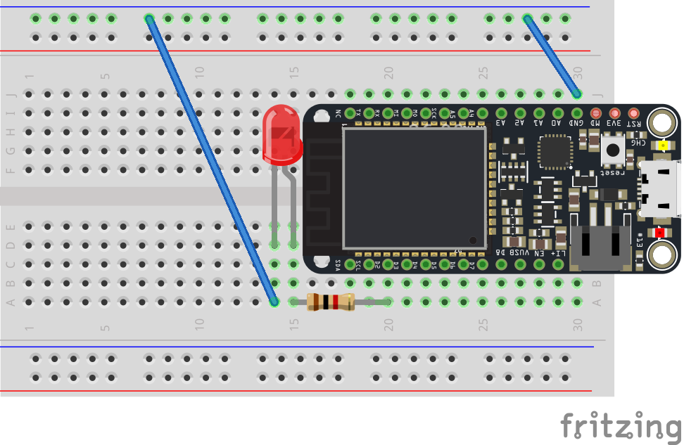
Circuit Diagram. Note the image does not correctly show the pin numbers.
Getting Ready to Program
Great. We have our circuit ready… now we can use Particle Build to tell it what to do.
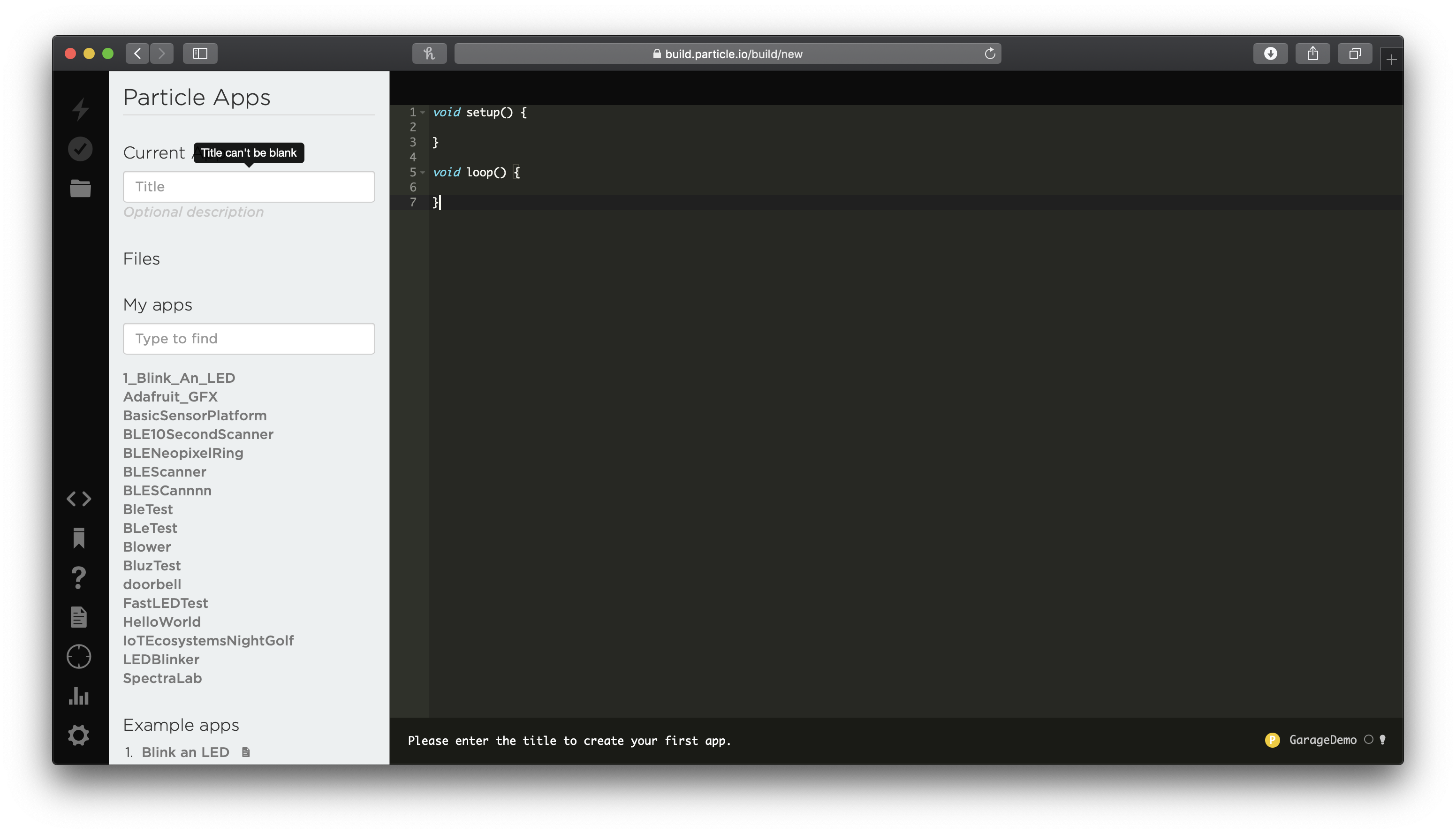
Once you load build, you should see a blank code window. Start by giving your project a title like: ‘HelloWorld’ or ‘IoT LED’ and press RETURN to save the project
Let’s quickly run through what you see here.
-
The Left hand sidebar contains a series of icons. These allow you to access common functions quickly
-
Lightning: Compile and deploy your program to your Particle Photon2
-
Checkbox: Check your code and find errors.
-
Folder: Save changes to your code projects.
-
Code: Move in and Out the Project window
-
Bookmark: Search and add libraries to your project
-
Question Mark: Get help / open quick reference
- Document: Launch the particle documentation in a new tab
-
Target: Select a device to work with. You should see your main device has a yellow star beside it. This is the device you will flash code to.
-
Graph: Open the Particle Console
-
Cog: Open your account settings
-
-
The Document Navigator shows a list of all the files in your sketch. Double clicking them will open them in the editor
-
The Editor allows you to create applications that run on your Partile Photon2 using the Wiring Language. You can have multiple tabs open at once.
-
At the bottom of the editor is a Status Bar. This contains important information on your sketch, its progress and things that you need to know to successfully get your sketch working.
-
Particle Cloud Status: Displays the status of the particle cloud if you are signed in and lets you know who you are signed in as. If you do not see your user ID, go to the ‘Particle’ menu bar and choose the ‘Sign in’ option
-
Devices: In the image above there are ‘No devices selected’ This is bad. In order to get your program working you need to tell the IDE what device (Photons) you are working with. Click on the label and you’ll be presented with a list of devices you have associated with your account, then select one!
-
Adding your first program
Now, let’s write some code.
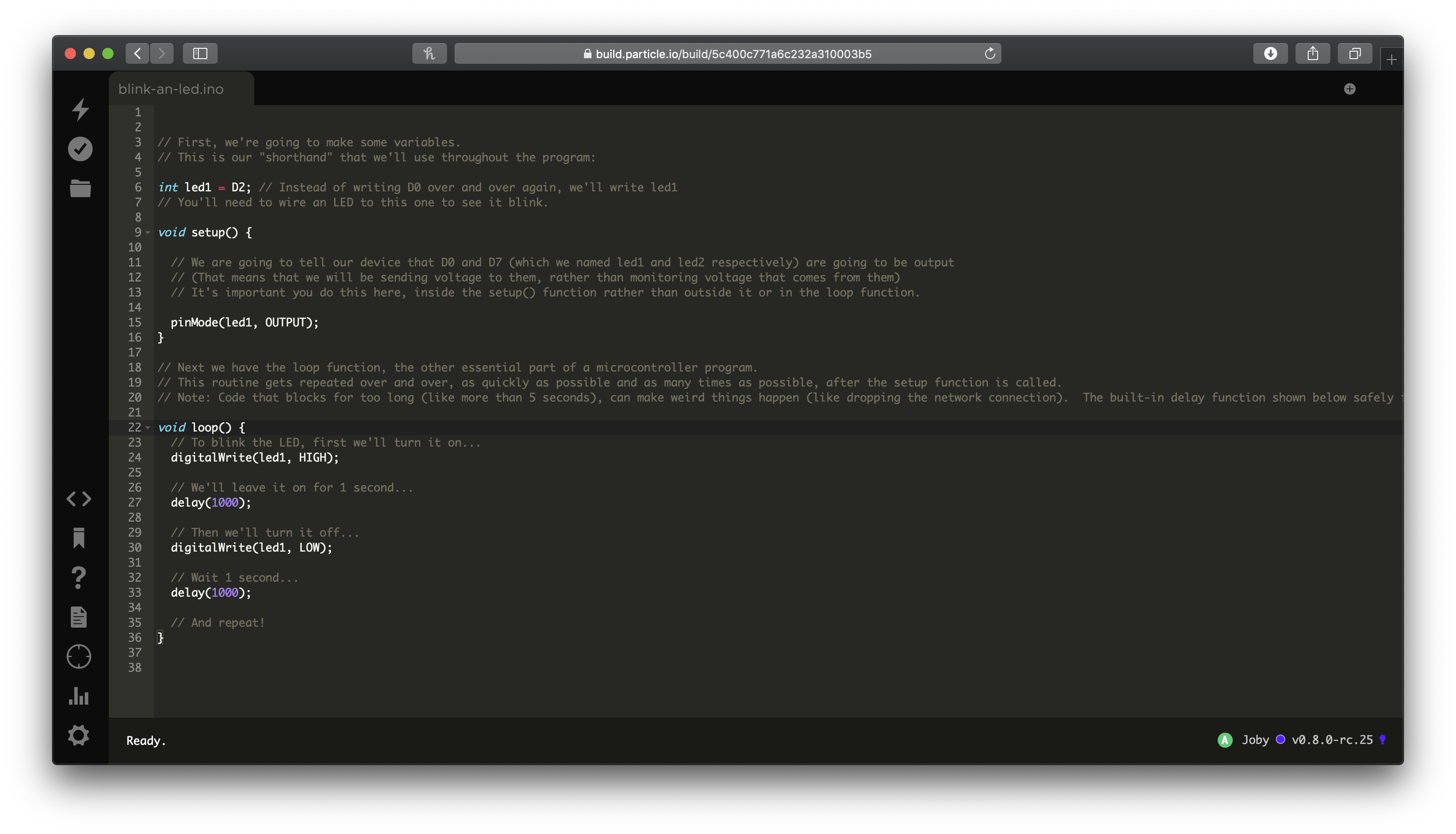
Coding in the Particle Dev
This is the program that you want to enter in the IDE. You’ll find the code for this example on the GitHub repository or you can feel free to just type it in from below.
Before we do that, let’s explore what’s happening here line by line.
Defining Variables
The first line of our program is the following.
int ledPin = D2;
We have declared a variable of type ‘integer’ and called it ‘ledPin’; that means that the variable called ledPin can only hold a whole number.
We’ve also assigned this variable a reference to pin D2. Basically, we’ve created a variable we can use to tell other stuff in the program that we want to do things with Digital Pin Zero.
Global Variables
Global variables are defined at the top of the program. Variables which exist outside of curly braces (‘{‘ and ‘}’) are known as global variables because any part of the code can make use of them.
Variables declared inside of curly braces (‘{‘ and ‘}’) can only be used by code which comes after their definition but before the outer curly brace. We’ll look at this again later.
Setting up our sketch
Every sketch needs two functions or blocks of code to exist. The first is setup() and the other is loop(). Setup is called once every time the program is run. This happens when the program is first put on the microcontroller, every time it is powered on and every time the reset button is pressed.
Microcontrollers, Sketches and Power
Every microcontroller has memory which stores the programs you put on it. Even if you remove the power the microcontroller still stores that program. When you plug it into power, it retrieves this program from memory and starts to run it again.
Only when you put a new program on the controller will the last one stop running.
Within the setup function, the microcontroller expects us to tell us how we want to use it. One of the most common things to do, is declare how the pins will be used. Digital Pins (and some other pins) can be used for input and output. So when we want to use a PIN we first need to say which of the two it will be used for.
The first command in our program does exactly this.
void setup() {
  // We want to tell the Photon that we'll use
  // D2 as an output pin.
  pinMode(ledPin, OUTPUT);
}
Remember that ledPin is a variable that maps to the digital pin zero (D2).
pinMode is a function that let’s us say what the pins will do. It takes two parameters or variables that can be passed to it: the pin we are dealing with, and if it will be used for INPUT or OUTPUT. To find out more look at: https://docs.particle.io/reference/device-os/firmware/#pinmode-
Functions + Curly Braces
Setup is a function. Every function will begin with an opening curly brace and finish with a closing curly brace. Everything in between is part of the function.
Finishing your lines
Notice how every line that does something in the program ends with a semicolon, ‘;’. This is really important. This tells the compiler that the line is terminated or that we are finished telling the the microcontroller about one of the things it should do.
If you forget to add a semicolon you will get errors when you compile.
A note on digitalWrite
We’re going to use a command called digitalWrite to control the pin at D2. It’s called a digital pin because its basically like binary, its either a 0 or a 1, on or off or in microcontroller speak “HIGH” or “LOW”.
A pin is basically like a faucet. Its connected to power from the USB that we plug in. This is like a pump. When can turn the faucet (pin) on, water (electricity) will flow out down the pipes (or wires). When you turn the faucet off, the flow stops. Simple.
digitalWrite takes two parameters or passed variables which tell it the pin we want to control and what the power should be set to (HIGH or LOW). See: http://arduino.cc/en/Reference/digitalWrite
Making it Blink
This is where the good stuff happens.
We’ve already setup our sketch. Now we need to fill in the loop() function. Loop gets called over and over and over and over. Once setup() finishes the microcontroller next executes everything inside the curly braces of the loop function. When it gets to the end (the closing curly brace), it will pause for a moment (a millisecond or two and that’s a very long time for a computer) and then start all over again.
To make the LED blink we’re going to do the following
-
We’re going to turn the power on (set it to
HIGH) -
we’re going to wait a second so that you can see the led on
-
then we’re going to turn it off again
-
we’re going to wait a second so you can see it off
-
then we’re going to let the loop loop over and over
So does this look in computer speak:
void loop() {
  // First... On
  digitalWrite(ledPin, HIGH);   // Turn ON the LED pins
  delay(1000);               // Wait for 1000mS = 1 second

  // Now... Off
  digitalWrite(ledPin, LOW);   // Turn OFF the LED pins
  delay(1000);               // Wait for 1000mS = 1 second
  // rinse + repeat

}
Let’s break this down:
-
digitalWrite(ledPin, HIGH)turns our LED on. -
We use the
delayfunction which takes an integer/number expressed as milliseconds (1000 seconds) to make the controller wait for a bit before moving onto the next line. -
digitalWrite(ledPin, LOW)turns our LED off. -
Then we delay again.
Looks like we’re ready to put this program on your microcontroller.
// Comments - Making programs human readable
Any text beginning with // is ignored. These lines are comments, which are notes that you leave in the program for yourself, so that you can remember what you did when you wrote it, or for somebody else, so that they can understand your code.
Compiling and sending to the Particle device
Make sure the Status Bar has a device connected and the Photon’s indicator is breathing blue. If not make sure your Photon is connected by USB and is getting a WiFi signal.
First, press the Folder icon to save your project.
Press the Lightning bolt on the top left of the window.
[If the Lightning bolt is disabled / greyed out, you might not have saved your sketch - see Step 2 for details]
You’ll see a message ‘Compiling in the Cloud’ and a few sections later your Photon should start flashing magenta.
Wait a few moments, it should return to breathing blue, and the LED should begin to flash!
Congratulations
You’ve just build your first circuit and written your first program to make it interactive. Below are some ways you can take it further.
Build your skills - Independent Exercises
Now let’s go beyond the basics and begin to explore how to develop circuits and control them. Below are three exercises that you can do to begin building skills.
Exercise 1
Modify the program to Blink on and off every 3 seconds.
Hint: You only need to make two changes. Read the comments to see where.
Exercise 2
Change the program to blink on and off 5 times then stop for 3 seconds. Each blink should be 0.5s (a half second)
Hint: An easy way to do this is to copy and paste. A better way to do this is with a for loop!
Exercise 3
Go back to the original program. Now add a second LED to the circuit.
Program the LED’s to alternate blinks i.e. when LED 1 turns on, LED 2 turns off, then when LED 2 turns on, LED 1 turns off.