Tutorial: Using a potentiometer
Table of contents
- What is a potentiometer?
- Using your potentiometer
- A simple dimmer switch
- Step 1: Create your Circuit
We’ve already looked at a couple of types of variable resistor - the force sensitive resistor and the photocell. Here we’re using manual input to adjust the resistance of the component. A potentiometer is essentially a dimmer switch. As you dial it down, it becomes more resistive, allowing less electricity to flow. When you dial it up, it becomes less resistive.

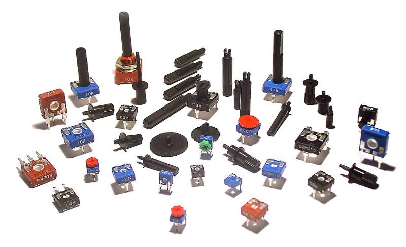
What is a potentiometer?
[shamelessly taken from https://learn.adafruit.com/adafruit-arduino-lesson-8-analog-inputs/variable-resistors-pots]
Inside the potentiometer, there’s a slider. This is what our analogPin is connected to and reading from. The slider moves along a circular track, and the track acts as a resistor. Turning the knob, moves the slider around the track. As it moves along, this track it increases or decreases the resistance and we can use this to determine the relative position of the slider.
Potentiometers don’t have to be circular. ‘Sliders’ which move along a track on a horizontal axis work with exactly the same principle and this guide works just the same for both components.
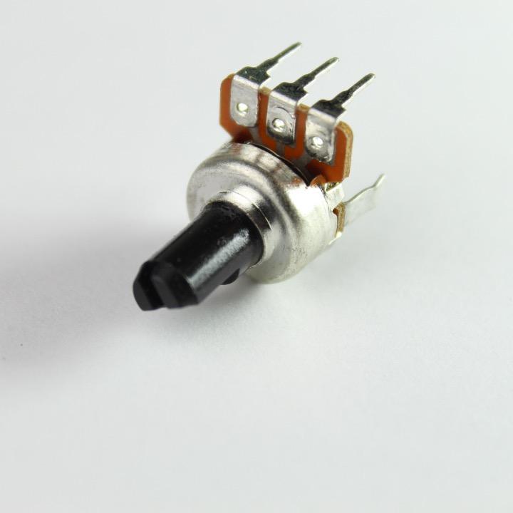
This is the potentiometer. It can be a little awkward to fit into a breadboard, so consider soldering new connections to the pins (don’t forget to color code).
Using your potentiometer
It has three pins. The outer two pins work much like any resistor - they can be connected in either direction and to either Ground or Power. The middle terminal is connected to the slider (or the bit that moves) allowing us to read it’s “position”.
When wiring a potentiometer, wire either left or the right terminal to ground; the remaining outer terminal to power (3v3) and the middle terminal to an analog pin you want to read from.
A simple dimmer switch
We’re going to wire up a pot. and allow you to fade up and down an LED as you turn the dial.
You will need
-
Particle Microcontroller
-
A single color LED (Light Emitting Diode)
-
A 10K Ohm potentiometer.
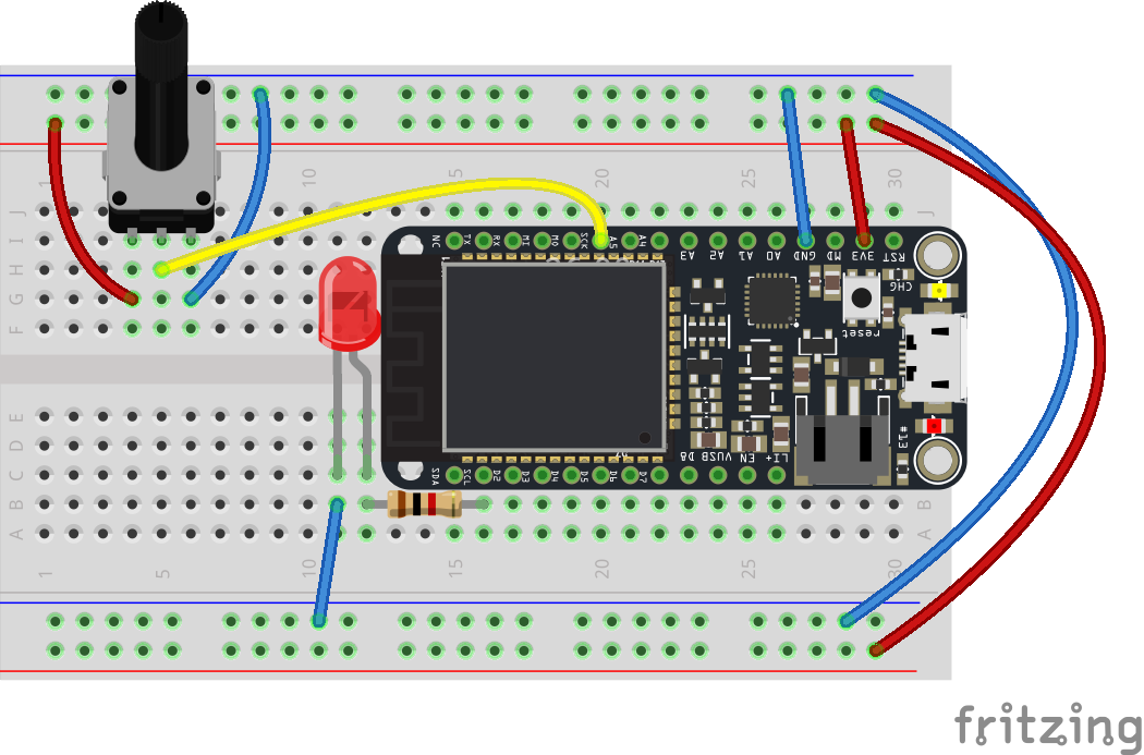
Step 1: Create your Circuit
The circuit, wiring and components are as follows:
Step 2: Setting up the Sketch
Our code is identical to the FSR - it’s another component that gives us a ranged set of analog readings / values!
// Define a pin that we'll place the pot on
int potPin = A5;

// Create a variable to hold the pot reading
int potReading = 0;

// Define a pin we'll place an LED on
int ledPin = D2;

// Create a variable to store the LED brightness.
int ledBrightness = 0;

//
void setup(){

  // Set up the LED for output
  pinMode(ledPin, OUTPUT);

  // Create a cloud variable of type integer
  // called 'light' mapped to photoCellReading
  Particle.variable("pot", potReading );
}

void loop() {

  // Use analogRead to read the potentiometer reading
  // This gives us a value from 0 to 4095
  potReading = analogRead(potPin);

  // Map this value into the PWM range (0-255)
  // and store as the led brightness
  ledBrightness = map(potReading, 0, 4095, 0, 255);

  // fade the LED to the desired brightness
  analogWrite(ledPin, ledBrightness);

  // wait 1/10th of a second and then loop
  delay(100);
}
Step 3: Compiling and sending to your microcontroller
Compile and rotate that dial!
Additional Exercises
Practice makes perfect… so try this out!
Exercise 1
Combine a switch (or button) and potentiometer. The switch should turn on and off the light while the potentiometer will fade up and down the light (but only when its on).