Tutorial: Using a switch
Table of contents
- What is a Switch?
- Using your switch
- You will need
- Step 1: Create your Circuit
- Step 2: Setting up the Sketch
- Step 3: Compiling and sending to your microcontroller
- Find out more

Believe it or not, we’ve already worked with a switch: a pushbutton is a type of switch. It is known as a momentary switch or a switch which is only active so long as they’re ‘actuated’ or pushed. Otherwise, they remain off. Saying momentary switches is technically right, but a bit of a mouthful, so we just say ‘buttons’ instead.
In this tutorial, we’ll look at maintained switches - or a type of switch that stays in a state until acted upon. A light switch or on/off switches are all good examples.
What is a Switch?
[shamelessly taken from https://learn.sparkfun.com/tutorials/switch-basics]
A switch is a component which controls the open-ness or closed-ness of an electric circuit. They allow control over current flow in a circuit (without having to actually get in there and manually cut or splice the wires). Switches are critical components in any circuit which requires user interaction or control.
A switch can only exist in one of two states: open or closed. In the off state, a switch looks like an open gap in the circuit. This, in effect, looks like an open circuit, preventing current from flowing.
In the on state, a switch acts just like a piece of perfectly-conducting wire. A short. This closes the circuit, turning the system “on” and allowing current to flow unimpeded through the rest of the system.
A circuit diagram with an LED, resistor, and a switch. When the switch is closed, current flows and the LED can illuminate. Otherwise no current flows, and the LED receives no power.
There are tons and tons of switches out there: toggle, rotary, DIP, push-button, rocker, membrane, … the list just goes on and on. Each of those switch types has a set of unique characteristics to differentiate it from others. Characteristics like what action flips the switch, or how many circuits the switch can control. Next up, we’ll go over some of the more basic switch characteristics.
Using your switch
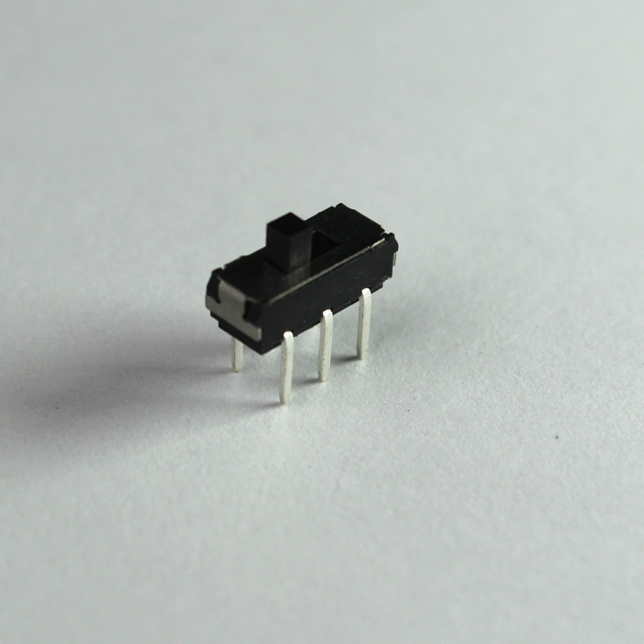
The switch in your kits (see above) is known as a double pole double-throw (DPDT) switch. It has 6 terminals and each side has 3 legs. Either sides terminals (legs) are wired separately, so it can be used to control two different circuits (double pole), but throwing the switch will affect both sides in the same way. More often than not, we’ll treat it as a ‘single pole’ switch.
When wiring a switch like this, we want to read from the middle pin. We wire this to our digital pins and use digitalRead to see if power is on it.
The simplest way to connect a DPDT or any three pin switch, is to only wire one side of the terminals. Let’s think about this… We could wire one terminal to power, one to the digital Pin and one to ground and changing the switch would change the flow of power…
But we can use the pull-up resistor connected to the digital Pin and one terminal connected to ground, to give the same outcome. If the switch it thrown towards the side wired to ground, we get a LOW signal and we know where the switch is set. If the switch is thrown to the unwired terminal, the pull up resistor will pull the digital pin to power and we’ll get a HIGH. Without wiring one terminal, we can still know the state of the switch…
Let’s try this.
You will need
-
Particle Microcontroller
-
A single color LED (Light Emitting Diode)
-
A double pole double-throw (DPDT) switch
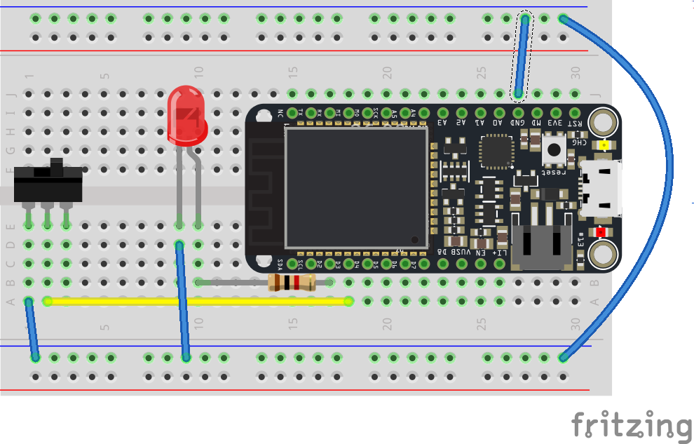
Step 1: Create your Circuit
The circuit, wiring and components are as follows:
Wiring to ground?
Notice that we’ve wired the pushbutton to ground, and not to power. This is because unlike sensors we can use an internal pullup resistor to get consistent readings from the pushbutton. You can find out more here: http://playground.arduino.cc/CommonTopics/PullUpDownResistor
Step 2: Setting up the Sketch
Guess what? Our code is identical to the pushbutton!
// We will be using D1 to control our LED
int ledPin = D2;

// Our button wired to D3
// We wire D0 to the middle terminal on the switch
// And any of the two other terminals to ground
int switchPin = D3;

void setup()
{

  // For input, we define the
  // switch as an input-pullup
  // this uses an internal pullup resistor
  // to manage consistent reads from the device

  pinMode( switchPin , INPUT_PULLUP); // sets pin as input

  // We also want to use the LED

  pinMode( ledPin , OUTPUT ); // sets pin as output

}

void loop()
{
   // find out if the button is pushed
   // or not by reading from it.
   int buttonState = digitalRead( switchPin );

  // Using a pulldown resistor we get a LOW
  // Signal when its on

  if( buttonState == LOW )
  {
    // turn the LED On
    digitalWrite( ledPin, HIGH);
  }else{
    // otherwise
    // turn the LED Off
    digitalWrite( ledPin, LOW);

  }


}
Step 3: Compiling and sending to your microcontroller
Compile and push your button!