RGB LEDs
RGB LEDs
LED’s are cool but RGB LED’s are even cooler. They let us to make rainbows - well just color.
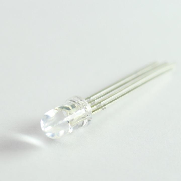
An ordinary LED has one light emitting component, RGB LEDs have three - one which emits red light (R) , one for green light (G) and one for blue (B). It works much like a pixel on your computer screen these three components combine to give us color. We can control their brightness with the analogWrite() function.
RGB LED’s have four pins, one for each color and either a common anode (+, 3V3) pin or a common cathode pin (-, GND).
Particle Maker Kits
In the Particle maker kit you have one RGB LED that uses a common anode (+) pin.
Wiring an RGB LED
Wiring a RGB LED
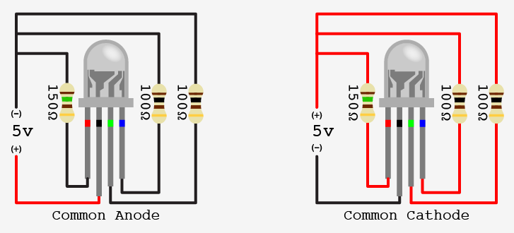
RGB LEDs are wired as illustrated in the diagram above.
The longest terminal (leg) will be the common anode or cathode.
With the anode/cathode nearest the left side, the left most terminal (leg) will be the RED terminal.
The right-most terminal will be BLUE, and the second from the right will be Green.
Each of the color terminals should be connected to a 1K Ohm resistor (brown, black, red) and then on to a PWM pin.
AnalogWrite + PWM Pins
Remember that PWM isn’t available on every pin on your Particle board. If you want to control an RGB LED you must have it connected to these pins.
Controlling an RGB LED: Worked Example
int redPin = D1;    // RED pin of the LED to PWM pin **D1**
int greenPin = A2;  // GREEN pin of the LED to PWM pin **A2**
int bluePin = A5;   // BLUE pin of the LED to PWM pin **A5**
int brightness = 0; // Full brightness for an CATHODE RGB LED is 0, OFF is 255

void loop()
{

  analogWrite(redPin, brightness);
  delay(500);  // wait for 500 milliseconds

  analogWrite(greenPin, brightness);
  delay(500);  // wait for 500 milliseconds

  analogWrite(bluePin, brightness);
  delay(500);  // wait for 500 milliseconds

  brightness = 255 - brightness;
}
The example will move through some basic color mixing with each iteration.