Using a photoresistor
Table of contents
- Using a photoresistor
This tutorial will introduce you to the basics of reading values from a photoresistor.
You will need
-
Particle Microcontroller
-
A single color LED (Light Emitting Diode)
-
A photoresistor.
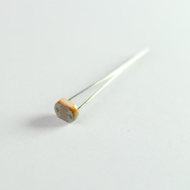
A photoresistor
Step 1: Identifying your photoresistor
Your photo resistor looks like this. You should have two of them in your Maker kit. A photoresistor is a light sensitive resistive sensor. That means that as light hits the top of the component it varies resistant to electricity. When there is a lot of light, it has a low resistance. When there is dim light, it is highly resistant.
Step 2: Create your Circuit
The circuit, wiring and components are as follows:
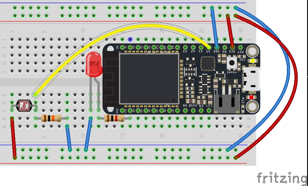
Fritzing Circuit Diagram
Wire up your LED as you did the last time.
Along your Particle board you will see a series of pins labelled A0 to A7. These are the analog pins which can be used to read from sensors.
First connect any terminal (leg) of your photoresistor to A0. Connect the other terminal to power or the 3V3 Pin.
We need to include a pull down resistor in order to get accurate readings. Do this by adding a 10K Ohm resistor to the terminal connected to A0. Connect this resistor to ground (GND).
Spot the Difference
There is very little difference visually between a 1K and 10K resistor.
Make sure you use the right one.
A 1K resistor is brown, black, RED while a 10K resistor is brown black ORANGE.
Step 3: Setting up the Sketch
Let’s get the basics of our sketch underway. We are going to combine all of the guides to do the following:
-
read from a sensor,
-
put the sensor reading on the Particle Cloud,
-
map that sensor reading to an output range, and
-
fade the LED to correspond to the sensor reading
If you’d like to get the code for this directly, go to
Add your variables
First we want to set a variable for the photoCell and set it to map to A0 (analog pin 0). We also want to create a variable to store any readings that we take from the photo cell.
We’re going to use D2 again for your LED, so set up a variable that maps to that pin at the top of your sketch. Also add a variable that we’ll use to track the brightness of the LED called ledBrightness;
// Define a pin that we'll place the photo cell on
// Remember to add a 10K Ohm pull-down resistor too.
int photoCellPin = A0;

// Create a variable to hold the light reading
int photoCellReading = 0;

// Define a pin we'll place an LED on
int ledPin = D2;

// Create a variable to store the LED brightness.
int ledBrightness = 0;
Setup setup()
Now, let’s specify the basics of our sketch. We need to configure pin D2 as output.
void setup()
{
  // Set up the LED for output
  pinMode(ledPin, OUTPUT);
}
Creating a loop()
In the loop we want to read the current value from the sensor, map that value into a usable range for output and fade the LED to reflect the sensor reading
void loop()
{
  // Use analogRead to read the photo cell reading
  // This gives us a value from 0 to 4095
  photoCellReading = analogRead(photoCellPin);

  // Map this value into the PWM range (0-255)
  // and store as the led brightness
  ledBrightness = map(photoCellReading, 0, 4095, 0, 255);

  // fade the LED to the desired brightness
  analogWrite(ledPin, ledBrightness);

  // wait 1/10th of a second and then loop
  delay(100);
}
Let’s walk through what is happening here. The function starts by using analogRead to read from pin A0. This gives us a value from 0-4095 stored in the variable named photoCellReading.
Next we use this variable and transform it to a range between 0 and 255 based using the map() function. The new value is stored as the ledBrightness. This is then used to fade the LED and finally the sensing pauses for a moment and repeats.
Connecting to the Cloud
The final piece of the puzzle is to make the light reading available through the Particle Cloud. To do this we add one line to setup() as follows.
void setup()
{
  // Set up the LED for output
  pinMode(ledPin, OUTPUT);

  // Create a cloud variable of type integer
  // called 'light' mapped to photoCellReading
  Particle.variable("light", &photoCellReading, INT);

}
This creates a new cloud variable named ‘light’ which is mapped to our existing sketch variable called photoCellReading and says it is an integer (or number).
Step 4: Compiling and sending to the Particle board.
Make sure the Status Bar has a device connected and the device’s indicator is breathing blue. If not make sure your device is connected by USB and is getting a WiFi signal.
Press the Lightning bolt on the top left of the window.
You’ll see a message ‘Compiling in the Cloud’ and a few sections later your device should start flashing magenta.
Wait a few moments, it should return to breathing blue, and the LED should be off.
Step 5: Seeing your Variable
Visit the Particle console, navigate to your device and check to see the value is displaying correctly.
Additional Exercises
Get some practice in!
Exercise 1
Currently the program shows how much light is available. When there is lots of light the LED is bright. When there is little light it’s dim.
Modify the program so that the LED shows the opposite. When there is little light, it will be bright and when there’s lots of light, it will be off.
Exercise 2
Instead of fading your light, why not turn it on or off when the light reaches certain levels.
For example, if the light levels are below 600 turn the light on (and bright), otherwise turn it off.
Modify the program to work in this way.