Using a Servo
Table of contents
- Step 1. Wiring a servo
- Step 2: Controlling a servo
- Step 3: Setting up the Sketch
- Step 5: Controlling it
- Find out more
In this tutorial, we’re going to wire up a servo to the cloud so that you can control it remotely by setting a variable. This will allow you to set the position of the servo from anywhere online.
You will need
-
Particle Microcontroller
-
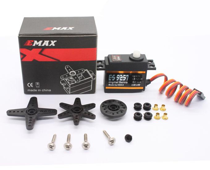
Servo
Step 1. Wiring a servo
The servo has three pins normally
-
Brown (or black) = Ground (GND)
-
Red / Orange = VIN (3v3)
-
Yellow/White = Signal
The signal needs a PWM pin to control it, so you can connect this to any of the following pins:
- On the Particle Core: D0, D1, A0, A1, A4, A5, A6, A7
- On the Particle Photon: D0, D1, D2, D3, A4, A5
- On the Particle Argon: D2-D8 + A0-A5
Finding Ground
Note: The Ground pin may vary as Brown or Black, +5V pin may vary as Orange or Red and Signal pin may vary as Yellow or White and sometimes Orange if there is already a Red and Black wire.
The circuit, wiring and components should look like this
Step 2: Controlling a servo
To control a servo we will make use of a built in Library that makes it really easy to position the servo there are a few main commands that we will use:
First, and up until now, we’ve used variables types like int, boolean and String. The library creates a new class or type of object that we can declare and use. This gives us access to all of the functions associated with the library on a particular pin. When we start using a servo we add the following variable declaration:
Servo myServoName;
Then, we need to tell the Servo library what pin we’ll be using it on and create all the needed stuff in the background to control the servo itself. We do this by using an attach() method to the setup().
myServoName.attach( pinNumber );
Finally when we want to use the servo itself, we use the write() method to tell it where to move the servo to. This takes an integer (a whole number) from 0 to 180 or the degree position to move it to.
myServoName.write(angle)
Now let’s put this into practice with the circuit above…
Step 3: Setting up the Sketch
Define the variables to use for the servo. Notice that we have used the Servo type to reference the library.
int servoPin = A3;
Servo myServo;
int servoPos = 0;
Next we setup and attach the servo
void setup() {

  // attaches the servo on the A3 pin to the servo object
  myServo.attach( A3 );
}
We’re going to control this with a cloud function so we don’t need to do much in the loop… nothing in fact
void loop() {
}
We create a new function to control the servo…
int servoControl(String command)
{
    // Convert
   int newPos = command.toInt();
   // Make sure it is in the right range
   // And set the position
   servoPos = constrain( newPos, 0 , 180);

   // Set the servo
   myServo.write( servoPos );

   // done
   return 1;
}
This function takes an integer and sets the servo position.
Now we need to add the function into the setup() so its available go back and add this:
void setup() {

  // attaches the servo on the A3 pin to the servo object
  myServo.attach( A3 );

   //Register our Particle to control the servo
   Particle.function("servo", servoControl);

}
One last thing we can do is make the servo position available as a variable in the cloud too
void setup() {

  // attaches the servo on the A3 pin to the servo object
  myServo.attach( A3 );

   //Register our Particle to control the servo
   Particle.function("servo", servoControl);

  // Keep a cloud variable for the current position
  Particle.variable(  "servoPos" , &servoPos , INT );


}
Step 5: Controlling it
Compiling the code and flash it to your Particle microcontroller.
Visit the Particle Console, navigate to your device and select ‘Show cloud functions’. You’ll then be able to type in a number and control the position of the servo.

