Motor Control: DC Motors, Solenoids, Fans and more
Table of contents
- For this tutorial
- Step 1. Wiring
- Step 2: Controlling the Motor
- Step 3: Setting up the Sketch
- Step 4: Controlling it
- Find out more
In this tutorial, you’ll find out the coding and wiring for actuators like motors, fans and solenoids. We’ll use the example of a solenoid but mostly you can swap out the code to control a heap of components in the same way. This includes
Images from Sparkfun. Product pages linked below.
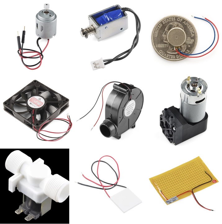
In the above image, the following a depicted:
- Top Left: A hobby motor
- Top Center: A solenoid
- Top Right: A vibration motor a.k.a. a vibrating disk
- Center Left: A DC Brushless fan
- Center Center: A Blower
- Center Right: A 12V vacuum pump
- Bottom Left: A solenoid valve
- Bottom Center: A Peltier Thermoelectric cooler
- Bottom Right: A Heating Pad
For this tutorial
You will need
-
Particle Microcontroller
-
A solenoid or one of the components mentioned above
-
A Diode
Step 1. Wiring
Motors (especially high powered ones) can draw a lot of current quickly. It’s not a good idea to have them directly connected to the pins on your board or you can blow the pin or the board itself. This means we’ll need another power source other than the board to get the needed current to our bigger motors. We’ll use a transistor to act as a middleman between the external power supplied to our motor and our Particle’s GPIO pins.
As outlined in the transistor guide, the 2N5192G Transistor has to be wired (with the the metal plate facing away):
- Wire the emitter (left-most terminal) to ground
- Wire the collector (middle terminal) to the ground terminal of the motor/actuator.
- Wire the other lead of the motor goes to the external power supply’s positive supply.
- Connect a 1k resistor
- Connect one side of the resistor to the base of the transistor (right most terminal)
- Connect the other end of the resistor to a GPIO pin on your Particle. You’ll drive this GPIO pin to HIGH to turn on the motor.
- Finally, add a diode between the ground and power of the motor. Diodes only allow electricity to flow in one direction and protects from reverse voltage spikes. Note the line on the diode. The line should always be closest to the collector (middle pin) on the 2N5192G Transistor.
The circuit, wiring and components should look like this:
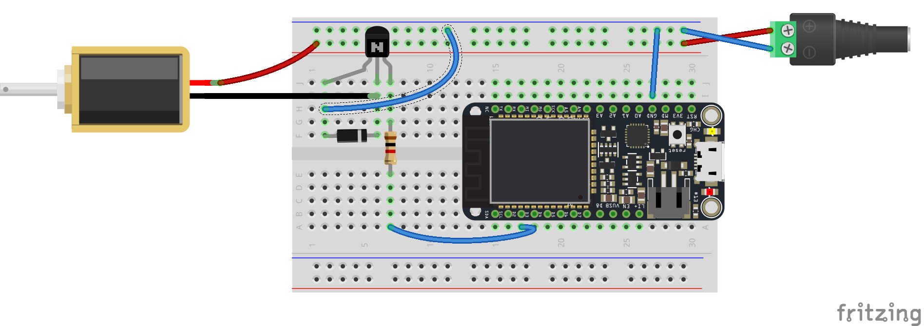
Wiring Diagram for Motors with the 2N5192G NPN Transistor
Wiring external power
Note: Take appropriate care when wiring in external power. It’s possible to damage your Particle if you create cross-connections or touch a live terminal to your board or components. Power down your Particle board and unplug external power before wiring or making changes. Read more here
Step 2: Controlling the Motor
With the transistor acting as a bridge between the two circuits we can control our component as with any other output on our board:
Use digitalWrite to turn power on or off. For example:
// Full power
digitalWrite( D2, HIGH );
Use analogWrite to control with PWM. For example:
// Half Power
analogWrite( D2, 127 );
Of course you’ll also want to set up your GPIO as an output
int motorPin = D2;

void setup(){
	pinMode( motorPin, OUTPUT );
}
Step 3: Setting up the Sketch
A simple block of code to have the solenoid trigger using a Particle cloud function will look like this:
int solPin = D2;

bool shouldActivate = false;

void setup()
{
  Particle.function( "activate", activateSolenoid );

  pinMode(solPin, OUTPUT);
}

void loop()
{
  if( shouldActivate ){
    doSolenoid(  );
    shouldActivate = false;

  }
  delay( 100 );

}

void doSolenoid(  ){
  for( int i = 0; i < 5; i++ )
  {
    digitalWrite(solPin, HIGH);
    delay( 100 ) ;
    digitalWrite(solPin, LOW);
    delay( 100 );
  }
}


int activateSolenoid( String command ){
  shouldActivate = true;
  return 1;

}
Step 4: Controlling it
Compiling the code and flash it to your Particle microcontroller.
Visit the Particle Console, navigate to your device and select ‘Show cloud functions’. You’ll then be able to type in a number and control the position of the servo.