Using the DB18B20 Temperature Sensor
Table of contents
This tutorial will introduce you to the basics of reading values from a DS18B20 Temperature Sensor.
A DS18B20 Temperature Sensor
You will need
-
Particle Microcontroller
-
A capacitor (see below)
-
A DS18B20 Temperature Sensor.
About the DS18B20
This sensor is known as a 1-Wire digital temperature sensor. The 1-wire refers to the way in which you talk to the sensor and get information from it. This ‘family’ of sensors uses a specific protocol for how you get information from it.
This means we need some special libraries to add to the ways our Particle device can interact with sensors.
You’ll need to download both from GitHub and copy the .cpp and .h files from the firmware folder to your project folder.
The sensor itself is pretty easy to wire up. You’ll notice is has three pins - one for power, one for ground and one for data (we read from this). We wire the digital signal pin to a digital pin on the Particle board.

Wiring a DS18B20
Look at the diagram below. Keeping the flat face towards you wire the left pin to ground, the middle pin to your Digital pins, and the right leg to power (3v3).
If you’re using the sealed temperature sensor in the kit the wiring is pretty similar. Red wire to power; black wire to ground; yellow wire to digital!
Finally, when you’re wiring the DS18B20 you need to add a pull-up resistor. Ideally use a 4.7 Ohm resistor (yellow, purple, red) but a 10K (Brown, Black, Orange) will do if that’s all you have. This is wired between the digital signal and power pin.
Pull-up resistor
A pull-up resistor weakly ‘pulls’ the voltage of the wire it is connected to towards its voltage source level when the other components on the line are inactive. It helps to give more reliable readings from inputs by avoiding ‘floating’ among other things. Read more at: https://learn.sparkfun.com/tutorials/pull-up-resistors
Step 1: Identifying the DS18B20
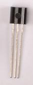
The temperature sensor looks like this. You can tell it is the DS18B20 as the flat face will have “DALLAS” etched in tiny letters on the top and directly below the number ‘18B20’. (You might need to catch the right angle to see this)
The DS18B20 is an easy to use one wire digital thermometer with up to 12-bit measurement resolution.
-
Supply Voltage: 3.0V to 5.5V DC
-
Current consumption: 4mA max
-
Measuring temperature range: -55°C to +125°C
-
Accuracy: ±0.5°C (from -10°C to +85°C)
-
Package: TO-92
Spot the Difference
The DS18B20 looks virtually identical to the NPN Transistor provided in the kits. Be sure not to confuse them - to make sure you have the right one, check the top right corner of the flat face.
Step 2: Create your Circuit
A cautionary note
The temperature sensor must be correctly wired or you will permanently damage the chip.
To wire it correctly, hold it with the flat face towards you. The left terminal (leg) should be wired to power (3V3). The right leg should be wired to ground (GND).
Do not mix them up. If you do, the chip will become extremely hot, it will become damaged and either give you no readings or incorrect values.
The circuit, wiring and components are as follows:
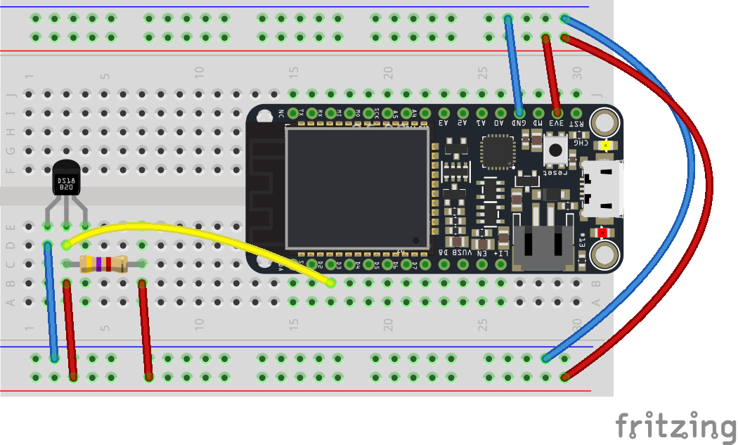
Fritzing Circuit Diagram
Ideally, the sensor should be placed away from the Particle board so that the heat dissipated by the board does not affect the temperature readings.
Step 3: Setting up the Sketch
Let’s get the basics of our sketch underway. We are going to combine all of the guides to do the following:
-
read from a sensor,
-
convert the sensor value into degrees Celsius and Farneheit
-
Put the converted sensor readings (temperatures) on the Particle Cloud
A note on supporting libraries
You’ll need to download and include two libraries for this code to work 1) the OneWire library and 2) the Spark Dallas Temperature Library. Include both in the same directory as your project.
Let’s take a look at the code and explain it.
// This #include statement was automatically added by the Particle Build IDE.
#include "OneWire.h"

// This #include statement was automatically added by the Particle Build IDE.
#include "spark-dallas-temperature.h"

// -----------------
// Read temperature
// -----------------

// Data wire is plugged into port 0 on the Arduino
// Setup a oneWire instance to communicate with any OneWire devices (not just Maxim/Dallas temperature ICs)
OneWire oneWire( D2 );

// Pass our oneWire reference to Dallas Temperature.
DallasTemperature dallas(&oneWire);

// Create a variable that will store the temperature value
double temperature = 0.0;
double temperatureF = 0.0;

void setup()
{
  // Register a Particle variable here
  Particle.variable("temperature", &temperature, DOUBLE);
  Particle.variable("temperatureF", &temperatureF, DOUBLE);

  // setup the library
  dallas.begin();
}

void loop()
{
  // Request temperature conversion

  dallas.requestTemperatures();

  // get the temperature in Celcius
  float tempC = dallas.getTempCByIndex(0);
  // convert to double
  temperature = (double)tempC;

  // convert to Fahrenheit
  float tempF = DallasTemperature::toFahrenheit( tempC );
  // convert to double
  temperatureF = (double)tempF;

  delay(5000);

}
The sketch starts by including the two needed libraries - OneWire and DallasTemperature.
Then, it declaring that the temperature sensor will use OneWire to read sensor values on pin D0 and sets the DallasTemperature library to use this configuration of OneWire. Finally, it says we will use two double (decimal type) variables to store the celcius and farenheit temperature readings.
The setup() links these two variables to a Particle Cloud variable and indicates that they are of type DOUBLE too. Finally, it initializes the Dallas Temperature sensor
Now to the meat of our program…
Each time the loop function is called it first reads the value from our sensor and stores it in a double variable. We store the celsius range in the variable named temperature, quickly convert to fahrenheit, and we’re done!
Step 4: Compiling and sending to your Particle board.
Make sure the Status Bar has a device connected and the device’s indicator is breathing blue. If not make sure your device is connected by USB and is getting a WiFi signal.
Press the Lightning bolt on the top left of the window.
You’ll see a message ‘Compiling in the Cloud’ and a few sections later your device should start flashing magenta.
Wait a few moments, it should return to breathing blue, and the LED should be off.
Step 5: Seeing your Variable
Visit the Particle console, navigate to your device and check to see the value is displaying correctly.
Additional Exercises
Exercise 1
Add a photocell to the circuit and post both temperature and light readings to the Particle cloud