Using a TMP36 Temperature Sensor
Table of contents
This tutorial will introduce you to the basics of reading values from a TMP36 Temperature Sensor.

A TMP36 Temperature Sensor
You will need
-
Particle Microcontroller
-
A capacitor (see below)
-
A TMP36 Temperature Sensor.
Step 1: Identifying the TMP36
The temperature sensor looks like this. You can tell it is the TMP36 as the flat face will have TMP etched in tiny letters on the top right corner. (You might need to catch the right angle to see this)
Spot the Difference
The TMP36 looks virtually identical to the NPN Transistor provided in the kits. Be sure not to confuse them - to make sure you have the right one, check the top right corner of the flat face.
Step 2: Identifying the Capacitor
What is a capacitor
A capacitor will try to keep the voltage in a circuit constant when there are changing currents. It conducts these changes to ground (GND). In this case we will use it to ‘filter’ and smooth the voltage from our temperature sensor so we get clean, consistent and good readings from it.
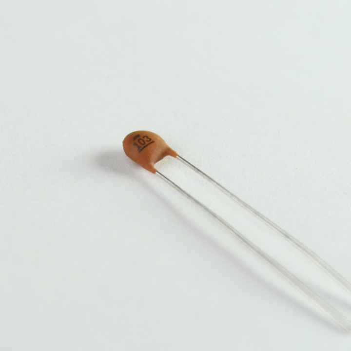
A Ceramic Capacitor
To keep the readings free of noise, we will add add a 0.01uF (10nF) ceramic capacitor.
The image shows the standard ceramic capacitors you have in your kit. They are widely used in analog circuits as bypass/ decoupling capacitors, in timers, filters, etc.
The kit comes with:
-
10nF (0.01uF) - Number code: 103
-
100nF (0.1uF) - Number code: 104
For this circuit you want the Ceramic capacity labeled 103
Note: These are non-polar capacitors which means they can be oriented both ways.
Step 3: Create your Circuit
A cautionary note
The TMP36 Sensor must be correctly wired or you will permanently damage the chip.
To wire it correctly, hold it with the flat face towards you. The left terminal (leg) should be wired to power (3V3). The right leg should be wired to ground (GND).
Do not mix them up. If you do, the chip will become extremely hot, it will become damaged and either give you no readings or incorrect values.
The circuit, wiring and components are as follows:
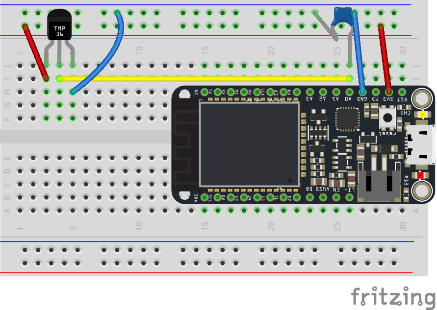
Fritzing Circuit Diagram
Note: the ceramic capacitor appears as the blue component connected at A0
No Pull Downs
This is a little different from the photo resistor and FSR. The TMP36 and other three terminal sensors don’t act like a resistor, so we need to connect them a little differently.
Three terminal sensors will have a Power Pin (connect to 3v3), a ground pin (connect to GND) and an output / reading pin (connect to an analog input pin, A0-A7)
Ideally, the sensor should be placed away from the Particle board so that the heat dissipated by the board does not affect the temperature readings.
Step 4: Setting up the Sketch
Let’s get the basics of our sketch underway. We are going to combine all of the guides to do the following:
-
read from a sensor,
-
convert the sensor value into degrees Celcius and Farneheit
-
Put the converted sensor readings (temperatures) on the Particle Cloud
If you’d like to get the code for this directly, go to
Let’s take a look at the code and explain it.
// Define the Pin the Temperature sensor is on
int tempPin = A0;

// Create a variable that will store the temperature value
double temperature = 0.0;
double temperatureF = 0.0;

void setup()
{
  // Register a Particle variable here
  Particle.variable("temperature", &temperature, DOUBLE);
  Particle.variable("temperatureF", &temperatureF, DOUBLE);

  // Connect the temperature sensor to A0 and configure it
  // to be an input
  pinMode(tempPin, INPUT);
}

void loop()
{
  // Keep reading the sensor value so when we make an API
  // call to read its value, we have the latest one
  int reading = analogRead(tempPin);

  // The returned value from the device is going to be in the range from 0 to 4095
  // Calculate the voltage from the sensor reading
  double voltage = (reading * 3.3) / 4095.0;

  // Calculate the temperature and update our static variable
  temperature = (voltage - 0.5) * 100;

  // Now convert to Farenheight
  temperatureF = ((temperature * 9.0) / 5.0) + 32.0;
}
The program starts by declaring that the temperature sensor will be connected on pin A0 and that we will use two double (decimal type) variables to store the celcius and farenheit temperature readings.
The setup() links these two variables to a Particle Cloud variable and indicates that they are of type DOUBLE too. Finally, it specifics that the pin at A0 will be used for Input.
Now to the meat of our program…
Each time the loop function is called it first reads the value from our sensor and stores it in an integer variable. This will give us a number between 0 and 4095. This number isn’t super useful yet so we’ll want to convert it into something more familiar, an actual temperature!
To do this, we calculate the original voltage. We take the sensor reading and knowing its connected to the 3v3* pin we multiply accordingly. Then we convert this by dividing by the maximum of the range. This gives us a decimal value to work with.
To get the temperature, we need to do a little more Math. 10mV is equivalent to 1 degree celsius so in order to convert the voltage to a more workable degree, we do the following. We know there are 1000 mV in a volt, and we have the number of volts already calculated. Or to say this another way for every volt the sensor gives off, there is 100 degrees celsius. Before we do the calculation we also know that there is a 500mV offset to the sensor. So we calculate as follows
temperature = ( voltage - 0.5 Volts ) * 100
We store the celsius range in the variable named temperature, quickly convert to fahrenheit, and we’re done!
Step 5: Compiling and sending to your Particle board.
Make sure the Status Bar has a device connected and the device’s indicator is breathing blue. If not make sure your device is connected by USB and is getting a WiFi signal.
Press the Lightning bolt on the top left of the window.
You’ll see a message ‘Compiling in the Cloud’ and a few sections later your device should start flashing magenta.
Wait a few moments, it should return to breathing blue, and the LED should be off.
Step 6: Seeing your Variable
Visit the Particle console, navigate to your device and check to see the value is displaying correctly.
Additional Exercises
Exercise 1
Add a photocell/resistor to the circuit and post both temperature and light readings to the Particle cloud
Find out more
https://learn.adafruit.com/tmp36-temperature-sensor/using-a-temp-sensor