Understanding your Argon
Shamelessly copied from an earlier version of http://docs.particle.io and adapted for Argon
Table of contents
- What is a Particle Argon?
- What do the Buttons do?
- What do the LEDs (Light Emitting Diodes - or lights) tell me?
- Pins
- PWM (Pulse Width Modulation) Pins
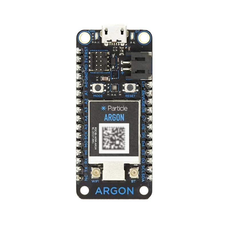
The Particle Argon (credit: Particle)
What is a Particle Argon?
The Particle Argon is a Wi-Fi development kit for internet-connected hardware. It is, in essence, the “brains” of a connected hardware product or project.
The Argon has on board a microcontroller, which is a small, low-cost, low-power computer that can run a single application. The microcontroller runs the show; it runs your software and tells the rest of the Argon what to do.
Microcontrollers are particularly good at controlling things; hence the name. They have a set of “pins” (little spider leg type things sticking off the chip) that are called GPIO (General Purpose Input and Output) pins, or I/O pins. They can be hooked to sensors or buttons to listen to the world, or they can be hooked to lights and motors to act upon the world. These microcontroller’s pins have been directly connected to the headers on the sides of the Argon so you can easily access them; specifically, the pins labeled D0 to D7 and A0 to A5 are hooked directly to the microcontroller’s GPIO pins.
The microcontroller can also communicate with other chips using common protocols like Serial (also called UART), SPI, or I2C (also called Wire). You can then make the Argon more powerful by connecting it to special-purpose chips like motor drivers or shift registers. Sometimes we’ll wrap up these chips on a Shield, an accessory to the Argon that makes it easy to extend the Argon.
The Argon also has a Wi-Fi module, which connects it to your local Wi-Fi network in the same way that your computer or smartphone might connect to a Wi-Fi network. The Argon is programmed to stay connected to the internet by default, so long as it can find and connect to a network.
When the Argon connects to the internet, it establishes a connection to the Particle Cloud. By connecting to the Cloud, the Argon becomes accessible from anywhere through a simple REST API. This API is designed to make it very easy to interface with the Argon through a web app or mobile app in a secure, private way, so that only you and those you trust can access the Argon.
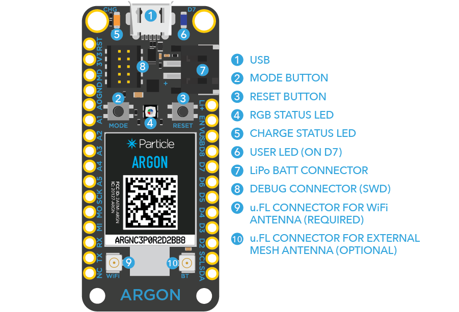
Diagram of the Argon board and it’s pins and buttons! (credit: Particle)
What do the Buttons do?
There are two buttons on the Argon: the RESET button (when holding the Argon with its USB-port to the top, it’s the button on the right) and the MODE button (on the left).
The RESET button will put the Argon in a hard reset, effectively depowering and repowering the microcontroller. This is a good way to restart the application that you’ve downloaded onto the Argon.
The MODE button serves a few functions:
-
Hold down the MODE button for three seconds to put the Argon into Listening mode to connect it to your local Wi-Fi network. The LED should start flashing blue.
-
To put the microcontroller into SAFE mode (where it boots up without loading any code you’ve flashed to it), hold MODE and RESET, release RESET and when the LED displays magenta release the MODE button
-
To put the microcontroller into DFU mode (where you can manually update the firmware via USB), hold MODE and RESET, release RESET and when the LED displays yellow release the MODE button
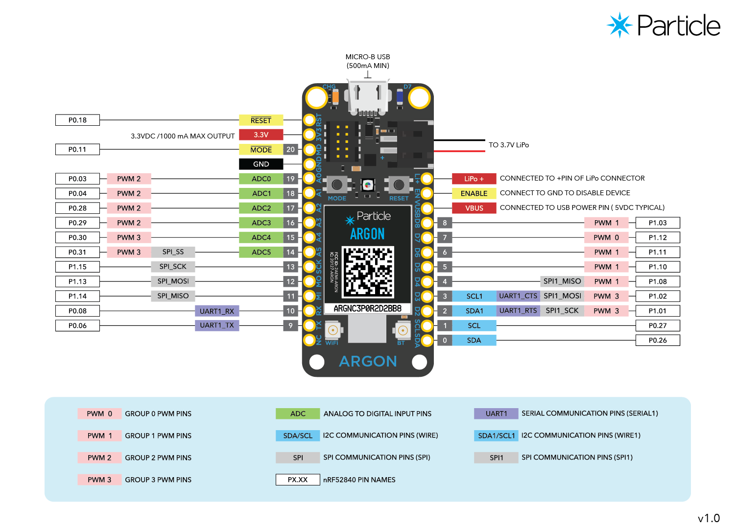
Diagram of the Argon board and it’s pins and buttons! (credit: Particle)
What do the LEDs (Light Emitting Diodes - or lights) tell me?
There is one main RGB LEDs in the middle that shows you the status of the Argon internet connection and device status.
The RGB LED could show the following states:
-
Flashing blue: Listening mode, waiting for network information.
-
Flashing green: Connecting to local Wi-Fi network.
-
Flashing cyan: Connecting to Particle Cloud.
-
High-speed flashing cyan: Particle Cloud handshake.
-
Slow breathing cyan: Successfully connected to Particle Cloud.
-
Flashing yellow: Firmware Update Mode, waiting for new code via USB or JTAG.
-
Flashing magenta: Updating firmware.
-
Slow breathing magenta: Safe Mode
-
Slow breathing white: WiFi Off
For an animated illustration of these states see: https://docs.particle.io/tutorials/device-os/led/argon/
The RGB LED can also let you know if there were errors in establishing an internet connection. A red LED means an error has occurred. These errors might include:
-
Two red flashes: Connection failure due to bad internet connection. Check your network connection.
-
Three red flashes: The Cloud is inaccessible, but the internet connection is fine. Check our Twitter feed to see if there have been any reported outages; if not, visit our support page for help.
-
Four red flashes: The Cloud was reached but the secure handshake failed. Visit our support page for help.
-
Flashing yellow/red: Bad credentials for the Particle Cloud. Contact the Particle team (hello@particle.io).
Pins
The Argon has 24 pins that you can connect a circuit to. These pins are:
-
VUSB: To power the Argon off an unregulated power source with a voltage between 3.6V and 6V, or, if you’re powering the Argon over USB, this pin can be used as 5V V~OUT~ to power external components. In this case consider the current limitation imposed by your USB power source (e.g. max. 500mA for standard USB 2.0 ports). Avoid powering the Argon via USB and V~IN~ concurrently.
-
Li+: This pin is internally connected to the positive terminal of the LiPo battery connector.
-
3V3: This pin will output a regulated 3.3V power rail that can be used to power any components outside the Argon. (Also, if you have your own 3.3V regulated power source, you can plug it in here to power the Argon).
-
GND: These pins are your ground pins.
-
RST: You can reset the Argon (same as pressing the RESET button) by connecting this pin to GND.
-
D2 to D8: These are the bread and butter of the Particle Argon: GPIO (General Purpose Input/Output) pins. They’re labeled “D” because they are “Digital” pins, meaning they can’t read the values of analog sensors.
-
A0 to A5: These pins are 6 more GPIO pins, to bring the total count up to 16. These pins are just like D2 to D8, but they are “Analog” pins, which means they can read the values of analog sensors (technically speaking they have an ADC peripheral). As with the Digital pins, some of these pins have additional peripherals available. A0-A5 are PWM-able
-
TX and RX: These pins are for communicating over Serial/UART. TX represents the transmitting pin, and RX represents the receiving pin.
-
SDA & SLC: Primarily used as data pin and clock pin for I2C, but can also be used as a digital GPIO.
-
MO,MI & SCK: Primarily used as SPI interface pins, but can also be used as a digital GPIO.
PWM (Pulse Width Modulation) Pins
When you want to use the analogWrite() function on the Argon, for instance to smoothly dim the brightness of LEDs, you need to use pins that have a timer peripheral. People often call these PWM pins, since what they do is called Pulse Width Modulation. All of the Argons Digital and Analog Pins can be used to perform PWM.
Next Up: The Particle Community